
Tools needed for the installation include a level; cordless drill w/ metric allen bits; framing square; metric allen wrenches; phillips screw driver; utility knife; pencil; tape measure and painters masking tape. A large tarp is also recommended to lay out tools and pieces to be assembled. This will reduce the chances of the tower being scratched during assembly and will keep all parts and tools in a confined area for better organization and ease of assembly.

A ball or semi ball shaped grinding stone for the cordless drill will also be useful.

A quick inventory of all the parts shipped should be step one. After unpacking all parts I realized the assembly instructions were missing. A quick call to Big Air produced a email with the instructions in a pdf file. Print, and I was good to go in less than 10 minutes. Customer service from Big Air was first rate during this installation.

The Ice tower came shipped in seven large segments, the top cross bar .......

2 one piece rear legs and the front assembly which included the 2 front legs and 2 angled mid sections that attached to the cross bar; rear and front leg assemblies. The pics below show partial assembly.

I went ahead and assembled all the major components of the tower it was very straight forward and quite simple. I suggest that the leg ends and the top hinge of the rear leg be attached loosely so these parts can be turned and manipulated during final installation.

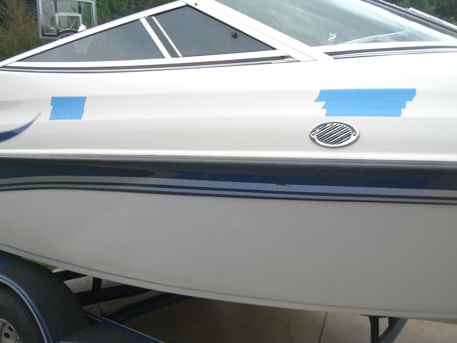
Once you have completed inventory and gotten the major segments assembled it's time to lay out the location of the tower. Ideally the tower should be mounted as high as possible on the deck. I wanted the front legs of my tower to be mounted just past the junction between the front windshield and the side windows. This is because I will later install a tower mounted bimini and did not want to get it to far forward. The pic below shows where I wanted to mount the front and rear legs using the masking tape. However, the deck of my Crownline 202 BR had too much curvature and would not allow the flat mounting plates to seat properly.

I reconsidered and moved the mounting points, and masking tape, down further on the deck This location on the Crownline 202 is slightly concave and much flatter than the upper portion of the deck. This allowed the flat edges f the mounting brackets to remain flush with the deck and the the rubber mounts to compress more easily. The front and rear legs are still in the horizontal location I wanted; but sacrificing about 2-4 inches of overall tower height.
This brings up a good point of discussion between the trade offs of "universal" fit and custom/semi custom towers. Universal fit towers will save you A LOT of money. But, you will sacrifice precise location as compared to custom towers. This was a sacrifice I was willing to take; otherwise, I would have spent $1000-$3000 more for a semi-custom/custom tower. YMMV
Once location of the tower was determined and I was satisfied the brackets would work; I inspected the back/underside of the deck to be sure it would be free of obstructions and that the backing plates would mount flush. All four areas were free of obstructions both port and starboard; it was now time to establish measurements. In order to duplicate the tower location to the port side it is important to establish a reference point that can be duplicated on both sides of the boat. I chose the joint of the front and side windshield; where it meets the deck as my point of reference.

Using the long edge of my framing square against and atop the bumper rail I aligned the vertical front edge of the square with windshield joint.......

and made a mark along the edge. A measurement of 10 inches forward to the bow put the center of my mount right about where I wanted it. I'm not real picky and didn't feel an inch or two either direction would matter. 10 inches made it a clean measurement that could be easily duplicated on the port side.


Once the center front measurement was established; I used the square atop the bumper again to draw a vertical line. This now is my center mark for the front mounting bracket.

I then used my tape measure and measured 50 inches toward the stern; made a mark; and drew another vertical line using the framing square in the same fashion as before. The Big Air installation manual recommended the legs of the Ice tower be 40-60 inches apart; I split the difference and made it 50 inches. No rocket science here. The 6 inch measurement written on the tape below is the measurement from the top of the bumper to the bottom of the bracket. The front bracket was 5 inches. This insured that both front and rear brackets would be in the same precise locations port and starboard. Once the starboard side was laid out I did the same for the port side.

Now that bracket centers had been located both port and starboard now it was time to mark and drill the deck for the mounting bolts. I centered the bracket and alined the bottom; then marked each hole using an extra fine sharpie.

This was done to all four bracket locations and double checked for measurement accuracy.

Now it's time to drill the holes. There are many opinions regarding how to drill fiberglass and I will NOT debate which is best. This is the way I do it and it really works well. I have never had gel coat chip; crack or split using this technique.
First, mask the area you want to drill. Second, choose the appropriate size bit for your thru bolts. In this case it is 1/4". Take the point of the bit and place in the center mark for the hole and press firmly and drill in reverse until you have a nice counter sink. Third, switch to forward and finish drilling the hole. Do this at low speed and let the drill do the work.

Your holes will be near perfect with no chips or cracking to the gel. Last, remove the masking tape and attach the the grinding ball and camphor the edge of each hole.


Once holes were drilled, I assembled and placed the mounting brackets to ensure proper alignment.

I then placed the backing plates and started the nuts. Sent my 15 y.o. son to the inside of the the boat with a 10mm box head wrench to hold the nuts while I tightened them with a screw driver and hex bit.

It is important not to tighten firmly so the mounts can be turned to the proper angle to accept the leg ends of the tower. Once the tower is atop the boat the brackets can be tightened.


You should have already assembled the tower into its 3 major sections; the cross bar ; and the port and starboard leg assemblies. Slide the cross bar over the leg assemblies (use the masking tape to cover the open ends of the cross bar, this will allow the bar to slide and adjust itself with out scratching the top ends of the leg assemblies)and lift the tower into place. This is a three man operation at minimum. Enlist the help of friends or put your teenage sons to work!


Once set in place and aligned, use the hex head wrench to tighten the bolts on the leg mounts and also send your helper under the deck to help you tighten the mounting brackets.


Next, align the cross bar so that it is centered. I measured from the center of the rear leg pivot point, to the outer end of the cross bar. Make sure the distances are equal on both sides. Align the tow knob so it is perpendicular; then use the masking tape to secure the cross bar in place.


Using the 4 predrilled holes on the cross bar as a guide; drill out all four holes; insert bolts through the drilled holes and tighten nuts in place.

Inspect all bolts and nuts; tighten any that remain loose. My Big Air Ice tower was a fairly simple installation and saved me hundreds to thousands of dollars over a custom tower. I couldn't be more pleased with the results.


The decision to install a wake tower is intensely individual. There are many options out there that run the gamut of cheap to expensive. Expensive does not always translate into better quality. Do your home work so that you don't regret the installation; no matter how much you choose to spend.


I just order the same tower. Im going to install it once i get back from afghanistan i was wondering how much give the tower has if any.
ReplyDeleteCongratulations! I think you will be very pleased with the performance of the tower. It is very rigid and sturdy and has held up without any issues through two very hard seasons of use.
ReplyDeleteThank you very much. I agreee with your article, this really helped me. I appreciate your help. Thanks a lot. Good website.
ReplyDeleteWindshield Repair Plano
Im going to install this tower on my Bayliner 185 this weekend. I'm glad theres people like you to document stuff like this to help others out.
ReplyDeleteI just installed the Big Air Vapor Tower. It's a few hundred dollars more than the Big Air Ice, but commentators have said it is stiffer so I went with it. I am ultimately pleased with it, but there are some weaknesses in the installation. One, I'd give the instructions a C-. A number of steps are missing and if you're not a pretty good mechanic you may get frustrated. Two, only flat aluminum backing plates are provided while I'd venture to guess the majority of installations will be on a curved surface. The instructions say to pound them into shape with a hammer if using them on a curved surface. Anyone with any metal working experience knows that this really doesn't work very well. You have to bend them into shape and if you don't have the tools, you're going to be frustrated. 1/4" aluminum takes a bit of effort to bend. Three, the double top tube makes it very difficult to drill the eight holes required to secure the legs to the top tubes. The top tube is pre-drilled in 8 locations (2 holes for each of the 4 leg tubes that will be inserted). The leg tubes slide into the top tube. How far they slide in is determined by the width of your boat (the beam). The leg tubes are, therefore, not pre-drilled. Using the pre-drilled holes of the top tube, one is supposed to drill through the leg tube on one side and, in theory, continue drilling through the leg tube on the other side, popping out through the pre-drilled hole on the other side of the top tube. The problem is that it is very difficult to hold your drill bit perfectly perpendicular so it will line up with the pre-drilled hole on the other side of the top tube. Chances are pretty good that you'll miss and end up widening the pre-drilled hole on the other side of the top tube, thereby substantially widening that pre-drilled hole. The solution would seem to be simply drilling from the other side using the pre-drilled top tube hole as a guide. That, however, is not as easy as it sounds because the distance between the two top tubes is so narrow that one can't get an average sized angle drill with a 7/16" bit between the tubes. There is no easy solution. I center punched the inside of the leg tube from the inside pre-drilled top tube hole then drilled a pilot hole in the leg tube. I managed it by chucking a 1/8" drill bit (which is a couple of inches shorter than a 7/16" bit) into my angle drill. I could just sneak the 1/8" bit and angle drill between the two top tubes. I then used that pilot hole to guide my 7/16" bit coming from the other side so the bit would come out precisely at the pre-drilled top tube hole. Finally, pay the extra dollars and get the anodized rather than the polished version. Polished aluminum really doesn't do well in a marine environment. While it won't corrode in fresh water, it starts looking bad pretty quick.
ReplyDelete